ESP8266 – Arduino IDE 예제 (GPIO 제어)
본 문서는 아두이노 개발환경(IDE)를 이용해서 ESP8266 모듈을 다루는 예제들을 포함하고 있습니다.
- ESP8266 – ARDUINO IDE 개발환경 설치
- ESP8266 – ARDUINO IDE 예제 (GPIO 제어)
- ESP8266 – ARDUINO IDE 예제 (WiFi 통신)
- ESP8266 – ARDUINO IDE 예제 (MQTT)
.
ESP8266을 위한 다양한 예제가 이미 갖추어져 있습니다. [Arduino IDE – File – Examples – ESP8266xxx] 예제들을 보면 다양한 기능들을 구현하는 방법이 나옵니다. 여기서 소개하는 예제는 NodeMCU V1 (ESP12E 기반) 보드에서 동작 테스트를 한 예제들입니다. 그리고 소개를 위해 예제 코드에 약간의 변형이 가해졌습니다.
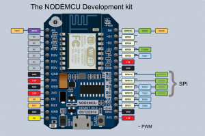
NodeMCU 보드는 아래와 같이 핀이 배치되어 있으며, 펌웨어 업로드를 위해 필요한 FTDI 모듈을 내장하고 있어서 PC에 USB 연결만 하면 사용할 수 있습니다.
.
Blink (Digital Output)
가장 쉽고 단순한 LED 켜기 예제입니다. 소스코드는 아래 링크에서 보실 수 있습니다.
LED 는 저항과 함께 NodeMCU 보드의 GPIO14 (D5) 핀에 연결하면 됩니다.
int LED = 14;    // Use D5, GPIO14

void setup() {
  pinMode(LED, OUTPUT);     // Initialize the LED pin as an output
}

// the loop function runs over and over again forever
void loop() {
  digitalWrite(LED, LOW);   // Turn the LED
  delay(1000);    // Wait for a seconds
  digitalWrite(LED, HIGH);  // Turn the LED
  delay(1000);    // Wait for a seconds
}
코드를 보시면 아실 수 있듯, 핀 번호 빼고 아두이노 스케치와 완전 동일합니다. pinMode() 함수를 이용해 특정 핀을 초기화 해줬습니다. 그리고 digitalWrite 함수로 3V 출력을 on/off 해줍니다.
아두이노 개발환경이 ESP8266 모듈을 지원하도록 만든 목적이 바로 이겁니다. 전 세계적으로 가장 보편화된 개발방법을 ESP8266 에도 적용함으로써 기존에 존재하던 수 많은 라이브러리를 쓸 수 있게도 해주고, 보다 쉽게 ESP8266 펌웨어 제작을 시작하도록 도와줍니다.
아두이노와 사용법은 동일하지만 한 가지 주의할 점이 있습니다. setup() 함수이후 loop() 함수는 무한 반복됩니다. 이때 loop() 함수가 한번 끝까지 실행되고 다음 loop() 함수가 실행되기전 ESP8266 의 복잡한 WiFi 통신 기능들을 처리하기 위해 ESP8266 core가 실행됩니다. 따라서 loop() 함수에서 너무 복잡한 작업을 처리해버리면 ESP8266 core가 충분히 자기 역할을 할 수 없습니다. 가급적 loop()를 빨리 처리하고 제어권을 넘겨줘야 합니다.
가이드에서는 loop() 안의 사용자 루틴이 50ms 이내에 끝나기를 권장합니다. 만약 이 이상의 시간을 요할경우 중간에 delay() 함수로 약간의 시간 간격을 주는 것이 좋습니다. delay() 는 사용자의 루틴을 잠시 멈추고 ESP8266 core가 동작할 수 있도록 해줍니다. (yield() 함수도 같은 역할을 하는듯 합니다.)
.
Button (Digital Input)
digitalWrite() 함수를 이용해서 LED 출력을 제어해봤으니 이번에는 digitalRead() 함수를 이용해서 디지털 입력을 받아보겠습니다. 버튼을 연결해서 클릭을 인식한 뒤, LED를 on/off 시키는 예제입니다.
버튼을 GPIO4(D2) 핀에 pull-down 저항을 이용해 연결합니다.
- ESP8266 GPIO14 ==> 버튼 다리 1
- ESP8266 3V ==> 버튼 다리 2
- ESP8266 GND ==> 10K 저항 ==> 버튼 다리 2
소스코드는 아래와 같습니다.
int LED = 14;    // Use D5, GPIO14
int BUTTON = 4;    // Use D2, GPIO4

void setup() {
  Serial.begin(115200);
  pinMode(LED, OUTPUT);     // Initialize the LED pin as an output
  pinMode(BUTTON, INPUT);     // Initialize the BUTTON pin as an input
}

// the loop function runs over and over again forever
void loop() {
  boolean buttonPressed = digitalRead(BUTTON);
  Serial.println(buttonPressed);
  digitalWrite(LED, buttonPressed);
  delay(100);  // Wait for a while
}
setup() 초기화 함수에서 버튼 입력을 받기 위해 GPIO 4번 핀을 INPUT 모드로 초기화 했습니다.
그리고 loop() 반복함수에서는 digitalRead() 함수로 버튼 상태를 읽습니다. 값은 HIGH(=true, 3V, 버튼 클릭) 또는 LOW(=false, 0V, GND, 버튼 릴리즈) 값으로 들어옵니다. 따라서 이 값을 그대로 digitalWrite() 함수에 전달해주면 버튼을 누를때마다 LED가 켜집니다.
.
Potentiometer (ANALOG INPUT)
이번에는 아날로그 입력을 받는 방법입니다. 소스코드는 아래 링크에 있습니다.
- https://github.com/godstale/ESP8266_Arduino_IDE_Example/blob/master/example/AnalogInput_Potentiometer/AnalogInput_Potentiometer.ino
아날로그 입력을 테스트 하기 위해서 포텐셔미터를 사용했습니다. 포텐셔미터를 ADC0(A0) 아날로그 핀에 연결하면 됩니다.
- 포텐셔미터 1 핀 ==> ESP8266 3V
- 포텐셔미터 2 핀 (가운데 핀) ==> ESP8266 ADC0(A0)
- 포텐셔미터 3 핀 ==> ESP8266 GND
그리고 소스코드를 올리면 시리얼 통신으로 포텐셔미터에서 읽은 아날로그 입력값을 출력해줍니다.
void setup() {
  Serial.begin(115200);
}

// the loop function runs over and over again forever
void loop() {
  int analog = analogRead(A0);
  Serial.println(analog);
  delay(100);  // Wait for a while
}
아두이노와 동일합니다. analogRead() 함수로 아날로그 핀의 전압 변화를 읽을 수 있습니다. 단, ESP8266 모듈은 아날로그 입력 핀이 하나(A0, ADC0) 뿐입니다.
소스에서는 시리얼 통신을 위해 Serial.begin() 으로 통신 초기화를 해줬습니다. 아두이노처럼 Serial.print(), println(), available(), read() 함수를 사용할 수 있습니다.
.
LED DIMMING (PWM – ANALOG OUTPUT)
이번 예제에서는 PWM을 이용해서 LED 밝기를 조절해 볼겁니다. 앞선 예제에서 포텐셔미터를 연결했으니 포텐셔미터로 LED 밝기 조절이 가능하도록 할겁니다. 소스코드는 아래에서 구할 수 있습니다.
앞서 사용한 LED, 포텐셔미터를 그대로 사용하시면 됩니다.
int LED = 14;    // Use D5, GPIO14

void setup() {
  Serial.begin(115200);
  pinMode(LED, OUTPUT);     // Initialize the LED pin as an output
}

// the loop function runs over and over again forever
void loop() {
  int analog = analogRead(A0);
  Serial.println(analog);
  analogWrite(LED, analog/4);
  delay(100);  // Wait for a while
}
PWM 사용은 간단합니다. setup() 초기화 함수에서 pinMode()로 LED 핀을 OUTPUT 모드로 초기화 합니다. 그리고 analogWrite() 함수로 값을 써주면 됩니다. (0~255)
포텐셔미터의 값을 읽는 analogRead() 범위가 0~1023이니 4로 나눠준 값을 analogWrite() 함수에 사용하면 됩니다.
.
기타 예제
위에서 소개한 간단한 예제 외에도 다양한 센서 사용을 위한 아두이노 라이브러리들을 사용할 수 있습니다. 아두이노 제어를 위해 레지스트리를 건드리지 않는 라이브러리의 경우 ESP8266에서도 문제 없이 사용 가능한 것으로 알려져 있습니다. 아래 라이브러리들은 ESP8266에서도 사용 가능한 (테스트 된) 호환 라이브러리입니다.
- Adafruit_ILI9341 – Port of the Adafruit ILI9341 for the ESP8266
- arduinoVNC – VNC Client for Arduino
- arduinoWebSockets – WebSocket Server and Client compatible with ESP8266 (RFC6455)
- aREST – REST API handler library.
- Blynk – easy IoT framework for Makers (check out the Kickstarter page).
- DallasTemperature
- DHT-sensor-library – Arduino library for the DHT11/DHT22 temperature and humidity sensors. Download latest v1.1.1 library and no changes are necessary. Older versions should initialize DHT as follows:
DHT dht(DHTPIN, DHTTYPE, 15) - Encoder – Arduino library for rotary encoders. Version 1.4 supports ESP8266.
- NeoPixel – Adafruit’s NeoPixel library, now with support for the ESP8266 (use version 1.0.2 or higher from Arduino’s library manager).
- NeoPixelBus – Arduino NeoPixel library compatible with ESP8266. Use the “DmaDriven” or “UartDriven” branches for ESP8266. Includes HSL color support and more.
- PubSubClient – MQTT library by @Imroy.
- RTC – Arduino Library for Ds1307 & Ds3231 compatible with ESP8266.
- Souliss, Smart Home – Framework for Smart Home based on Arduino, Android and openHAB.
- ST7735 – Adafruit’s ST7735 library modified to be compatible with ESP8266. Just make sure to modify the pins in the examples as they are still AVR specific.
- Task – Arduino Nonpreemptive multitasking library. While similiar to the included Ticker library in the functionality provided, this library was meant for cross Arduino compatibility.
- UTFT-ESP8266 – UTFT display library with support for ESP8266. Only serial interface (SPI) displays are supported for now (no 8-bit parallel mode, etc). Also includes support for the hardware SPI controller of the ESP8266.
- WiFiManager – WiFi Connection manager with web captive portal. If it can’t connect, it starts AP mode and a configuration portal so you can choose and enter WiFi credentials.
- OneWire – Library for Dallas/Maxim 1-Wire Chips.
- Adafruit-PCD8544-Nokia-5110-LCD-Library – Port of the Adafruit PCD8544 – library for the ESP8266.
인터넷을 검색해 보면 이 외에도 주요한 센서들의 예제를 구하실 수 있습니다.
.
참고자료
